I bought a rather expensive ($19.95) tip for the soldering iron from Jaycar during the week. It is the right diameter and has a hollow centre but it is too long and the nut holding it into the soldering iron can’t reach the screw thread to lock it in place. Waste of money. Raymond managed to clean the old tip and re-tin it and it now works but it is still not perfect. He found a source for the tips in the UK but they will not post to Australia. We have friends living in the UK so could send some money over to them to buy the soldering tips for us and post them out. Easy!
Friday morning we started laying some track. We started with the first turnout into the yard from the back end of the shed (western end of the shed). Raymond then laid the first section of flex-track and the second turnout. He then laid the flex-track for the main line and passing loop about half way along the yard towards the end of the first sheet of plywood we had laid. Raymond had spent some time in laying a nice, easy “S” curve into the main line station track.
 Raymond laying the main line loop past the proposed station area. The turnout leading to the passing loop can be seen on the left. This is the turnout at the western end.
 Raymond tapping in another track pin as he lays the main line loop.
 By late Friday afternoon Raymond had completed the first half of the main line and passing siding loops. He then placed his two D&RGW 0-4-0DM locos on the track.
Friday afternoon we spent in cutting to length some more 4” X 1” joists and installing them to support the second half of the station yard. We then selected the next piece of plywood and secured that in place. I then drew the track centre lines continuing the main line and passing loop to the turnouts at the eastern end of the yard. Raymond also “played around” placing his two AMS brass models of the D&RGW 0-4-0DM No.50 side by side on the main line and passing loop. Looking at these, my mind started to get a little “niggly”. There was something wrong. Joists installed ready for the plywood to be placed and track laying on the second half of the track extension.
Saturday morning we paid our usual visit to see my father and then over to Austral Modelcraft where I bought another three turnouts and Raymond bought a couple more Chooch loads for wagons to add to those he already has. After lunch Saturday, we started work again. Raymond finished the loop and had laid the first turnout at the eastern end of the yard. It was all coming together very well and we were following the plan. It was perfect. Too perfect!
Raymond had left the two 0-4-0DM locos on the track and I looked at them again. I had “stewed” about this overnight and it was still worrying me – there was something that didn’t look right. I went back to the NMRA Standards sheet S-8 and yes it said for On3 and On30 track centres on straight track were 3 inches and that is what I had planned for and that it is what we had. I used the NMRA On30 Standards Gauge to check and yes we had the same for both tracks the gauge would meet exactly in the middle between the two tracks. That still doesn’t sound right. Raymond removed his two diesels and we placed a K-36 and K-37 2-8-2 side by side. They were close – Very close. In fact with one loco slightly lower in over all height the window shades over the cab windows were one above the other – THEY OVERLAPPED!! If you allowed for the inevitable side to side twisting motion of a long loco they would come into contact even more. Disaster – but I had designed and we had laid the track to the NMRA Standards – or had I? This is what it looked like when the track centres were at 3 inches with a K-36 and a K-37 side by side.
 Too close for comfort.
Raymond sat down with me to have look over the NMRA Standards again. “What’s this little asterix here mean?” – says Raymond. There it was in the On3/On30 Column for straight track clearances – M*.
I had looked up M* which said that M = 2 X A with the A coming from the NMRA Track Gauge. A = 1 ½ inches therefore 2 X A = 3 inches. So I was right with 3 inch track centres. Hang On!! There was some additional fine print at the end of the S-8 Standard that said if you are using K Class locomotives you need to use the appropriate Standard Gauge clearances column as they were such big locomotives. Now THAT column says the clearance should be 3 ¾ inches. It pays to read the fine print.
Raymond was not too happy with me – I can tell you. Feeling somewhat chastened I timidly suggested he take up the turnout at the eastern end and the passing loop back to the curve into the loop at the western end and we relay the track at an extra ¾ inch width to make it 3 ¾ inches track centres. While he did this, I had to cut another 2 inch wide strip of plywood as the new location would have placed the track half off the edge of the current plywood board.
Well, suffice to say by the end of Saturday afternoon we had secured the additional 2 inch wide strip of 12 mm plywood and relaid the track along the loop siding up to the first turnout at the eastern end of the yard. We will lay that turnout and the rest of the turnouts on Sunday.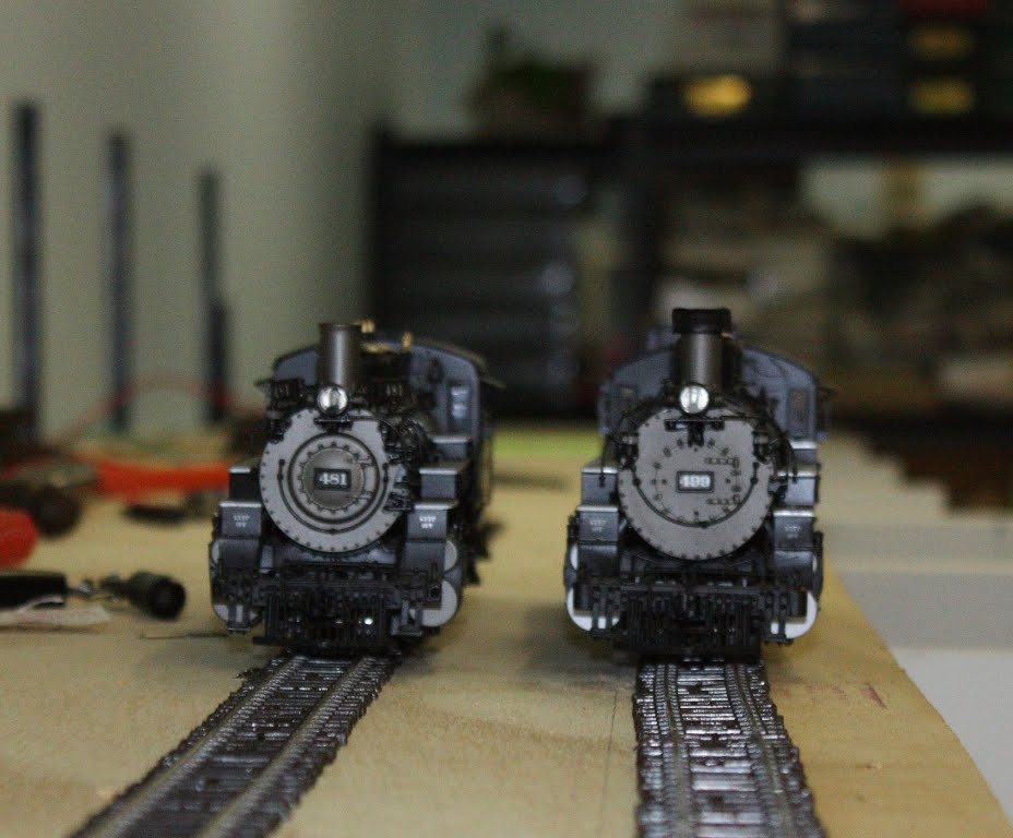 Its amazing what an extra 3/4 inch will do. The K-36 and K-37 on the section of track with the loop relaid to 3 3/4 inch track centres
 I wish I had an extra 3/4 inch.
 The relaid passing loops have been completed and the pointwork for the eastern end of the yard is progressing.
Sunday started out fine. We finished laying the four turnouts for the main line and main line loop. I cut some more 12 mm thick ply 200 mm wide (by 2400 mm long) and installed it along the front edge of the baseboard framework. This will accommodate the mining branch loop. The ply has been laid along the front of the baseboard framework has been secured and track centre lines marked out ready for Monday.
We had visitors for a few hours in the middle of the day so didn’t get a lot more done. Later in the afternoon, Raymond started installing the Cobalt DCC motors for the turnouts. He got two done fairly easily but the third started to cause him problems. Screw heads these days and screw driver tips are made of softer alloys than years gone by so they burr over easily. The motor we were trying to install lies directly over an L-Girder, I had designed the track layout so as to avoid these L-Girders, the joists and metal wall brackets. This turnout was on the track that we had moved out by ¾ inch and thus created the problem
I will be going to Bunnings first up tomorrow to purchase more screws to mount the Cobalt motors (hopefully better quality than those supplied with the motors – Yeahhh right!!). I will also be purchasing a couple of smaller sheets of plywood (1200 X 600), a couple more Stanley long shank Phillips Head Screwdrivers (like the old song goes – the old grey mare she ain’t what she used to be – the old Stanley screw drivers they ain’t what they used to be) and will see what soldering tips they might have. Finally, I might have a look at an electric screw driver.
Raymond was getting a bit frustrated (he talks to himself a lot when he is like that) so we called it a day. More tomorrow.

try Altronics? I just mail ordered tips for my Micron soldering station.cheers Nick
ReplyDeleteThanks Nick we'll do that
ReplyDeleteDavidM